Controller wiring
1. Connect one wire on each valve together to 1 wire on 24VAC transformer.
2. Connect the other valve wires to each of the numbered terminals.
3. Connect the other wire on the transformer to terminal on controller marked COMM
4. Plug 7.5-15VDC to jack on controller
5. (optional) Plug external sensor into RJ-11 jack
6. (optional) Plug in external back up power
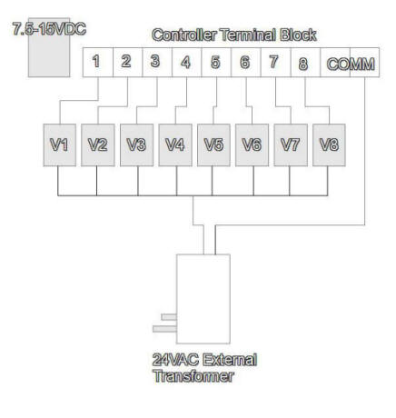

External sensor jack
Terminal block for wires
7.5-15VDC JACK
Back-up power jack
Alternate method
In the event you do not want to remove existing controller, you can run both controllers to add more
starting times. Obviously, you would'nt want to run both controllers at the same time or even overlap, but it
will not make if a difference if it happened provided both systems are using the same 24VAC transformer.
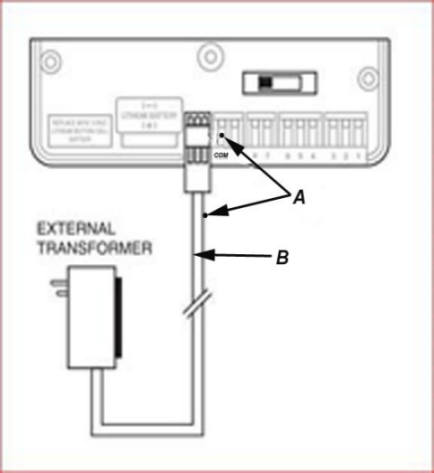
I you do this, you must determine which input of the 24VAC goes to the individual valve terminals on existing
controller. This is accomplished by checking for continuity from input of transformer to common terminial on
existing controller. Unplug power and using continuity checker or multi-meter, determine if wire A or wire B is
conneted to existing common.
EXAMPLE: If A is connected to existing common as the pictures shows, then the B wire would be connected
to the COMM terminal on the JanProducts controller.
Then jumper wires would be run from existing controller (1-8) to JanProducts controller(1-8)
as shown in picture at left
To COMM on JanP Controller
Existing (1-8)
Jumper wires to JanP
controller (1-8)