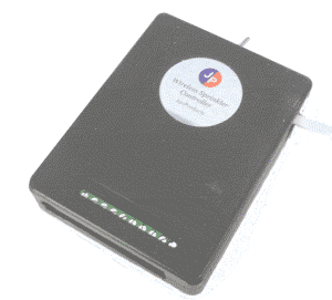
WIRELESS RELAY CONTROLLER
J
A
N Products
Henderson, NV 89015

Controller software installation instructions for PC
Software Installation Instructions for Windows
Download file named “Model800v1.zip" from janproducts shopping cart.
Unzip file (Folder can be anywhere on computer. It is recommended to put folder in Documents folder)
Determine bluetooth comm port number.
The txt file "jansettings.txt" can be edited by notepad if you want to make changes with a new data load. For instance, if Windows changes the comm port, you can edit commport text with current setting. You can also change port number when running loading program. If changes are made to text files, be sure not to change format of file, as this will cause unwanted results when data is uploaded. It is important not to change the format. Each line from 1-8 is a relay time. Times go from 1 to 200, with 200 equal 33 minutes, 60 would equal 10 minutes, etc. Lines 1-7 also control the days. If 300 is added to the time on line 2, the relay will run on Monday, as the week starts on Sunday. (Example- line 2=360 means relay will turn on Monday for 10 minutes.) Start times are controlled by the last 4 lines with number 1to 24.
Controller Wiring Installation Instructions
Controller Hardware Wiring Installation (See Controller Diagrams page)
PC Controller can be installed either in parallel to an existing sprinkler system or as a stand alone.
If you are installing as a stand alone system, all that is necessary to do is connect one side of your valve transformer to the common side on the relay board and the other wire to the common side of your valves. See digram below.
If you installing as a parallel to existing system, you need to determine which of the transformer terminals on your controller is going to ground and which is going through the controller's internal switching. This is done by first unplugging your valve transformer and then disconnect the wires from the controller. Run a continuity check from each “power in” terminal screw to the terminal marked “common” on the controller(points marked “A”). The terminal that is NOT common is the terminal you will connect to the relay board(point marked “B”).
Next wire the valve terminals to the corresponding numbers on the relay board.
Plug the supplied 12v transformer to the jack on the bluetooth board.
Plug in the valve transformer.
Once you have determined which terminal is correct, you can wire per the drawing. Preliminary jumpers and wires have already been installed.
Wiring Diagram for stand alone system
(See Controller Diagrams page)
Note: External transformer is not supplied. Transformer can be obtained from your garden center or local home improvement center.
